Prior to April of 2018, our only boondocking experience in the first 20 months of traveling the country in our RV, was 3 nights at a state park in Rhode Island, and one night at a truck stop parking lot in Laramie Wyoming. The weekend spent in George Washington State Park near Providence Rhode Island was spent outside, playing in a lake, enjoying the warm summer weather, and our only electrical needs were for the lights. On the other hand, the 1 night in the Laramie Pilot’s parking lot was a cold Wyoming October night in which running our furnace to stay warm killed the one battery we had. The furnace draws a lot of energy, and running all night would kill any single 12v battery in a matter of hours. That wasn’t the moment we decided to get more batteries or anything like that, it was just our only experience with camping off grid for any amount of time with our Cyclone. Now don’t get me wrong, I would have loved to upgrade that system immediately, but we had bigger plans for the following year. FYI, this post does include affiliate links!
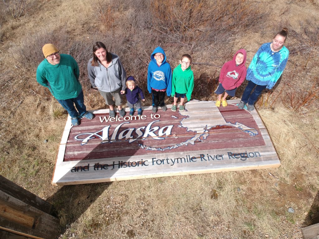
Alaska!
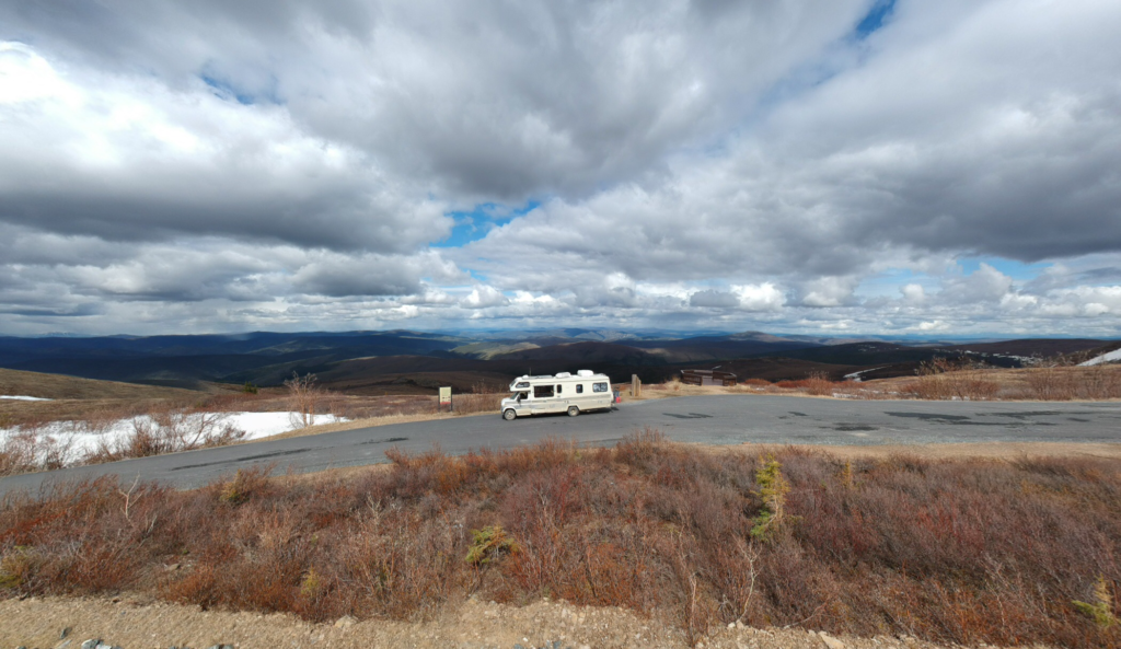
It’s no secret that we went to Alaska in the summer of 2018, and because we chose to buy an old small motorhome (dubbed the Summer House) to take, so any upgrades or modifications to the Cyclone were on hold. We also used the “Summer House” as a test for our solar needs. We went very simple and cheap in that system since it would be a 4 to 5 month trip, and it would be sold right away.
The Summer House’s System:
- 3 x Costco Deep Cycle Batteries, the cheapest they had!
- 3 x 100 watt Windy Nation solar panels (with tilting brackets that I didn’t tilt even once)
- 30 Amp Windy Nation Solar Charge Controller
- 3000 Watt Windy Nation Inverter

I’m sure you can see a trend forming here. I bought as much as I could from Amazon, which kept the project as cheap as possible. Windy Nation seemed to have the market cornered on Amazon RV Solar, so I went with them.
To get the power out of the batteries, I added 2 standalone outlets directly to the inverter, one in the kitchen for our Instant Pot, and the other in an easy spot to access for charging and whatever else we needed it for. This system was very simple, and definitely worked great in this application. Even though the sun never sets in Alaska, we definitely struggled with the 3 panels on the roof since it was overcast and cloudy most of the time. Luckily we could charge the batteries a few different ways:
- Solar panels, when the sun happen to be out
- Alternator, when the motorhome’s engine was running
- With the on board generator
We traveled in the Summer House from April 15th to August 25th and in those 4 ½ months I definitely learned a lot about powering an RV solar off the grid. If I were to go back and design a Summer House system again, I would do it very similarly. Maybe an additional battery (and better batteries), another panel or 2, and be more conscious of the size and length of wiring I used for the various connections throughout the system. Overall it was a great cheap solution that worked.
What did we learn?
The main takeaway from that experience was we did NOT want to be dependent on 2 isolated outlets; we wanted our RV to function the same whether it was plugged in or not. At least as long as there was battery life!
What did we want?
So I had my solar mission statement, and now the research phase started. This is a rabbit hole like you have never seen! There are so many ways to skin this cat that my head was spinning. I was researching panels, inverters, inverter/chargers, charge controllers, batteries, wiring, breakers, battery monitors, etc…. There is a wealth of information out there, but it was all in some foreign language that talked in terms of watts, ohms, volts, amps, gauge wiring, hybrid, assist, bluetooth, Wi-Fi, and the list goes on and on!
We bought a Kill-a-watt electricity usage monitor, started measuring our energy consumption and completed an energy Audit.
*If you are thinking about putting together a system for your RV, an energy audit should be the first thing you do!
So I figured out something that was not surprising to me, although there are many of us, and we have a large RV, we are not particularly heavy users. But we have the capability very quickly to use a lot of electricity.
When thinking through the process, and what we wanted to accomplish with the system, I kept thinking back to our solar mission statement from the Summer House, we wanted our RV to function the same whether it was plugged in or not!
My disclaimer: I am great with DC electrical systems, but know only enough about AC systems to be dangerous. I am not afraid to ask questions (I asked many) and find out the right answers! I spent countless hours reading blogs and resources about RV solar power builds. This blog is NOT meant to be an absolute resource for powering your RV, but more to document our build and journey to being energy independent.
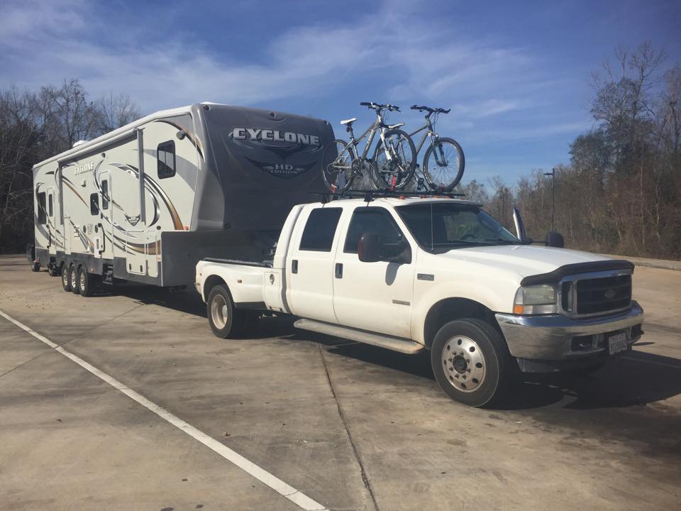
I mentioned above, our 40’ toy hauler 5th wheel came from the factory with a single 12 volt battery. We had replaced it in the previous year, and honestly hadn’t really used it for much since we were always plugged in. Since solar was still in very early planning phases, I did not want to spend too much on a battery bank that would probably be upgraded sooner or later. I opted to go with 4 x 6 volt Trojan T-105 golf cart batteries for the time being. They are rated at 225 amp hours each at 6 volts, so 2 sets of 2 wired in series then together in parallel, gives us 450 amp hours at 12 volts. This isn’t super spectacular by any means, but these are very good, reliable batteries, and fit well into our existing battery compartment.
What did we start with?
Our 2011 Heartland Cyclone 3612 toy hauler is a 50 amp RV, if you know anything about RV electrical systems, you know that there are 2 types of systems, 30 amp, and 50 amp. Here is a very basic rundown of the differences between the 2 systems:
- The plugs on RVs with 30 amp and 50 amp are different in design.
- A 30 amp plug has three prongs – a 120-volt hot wire, a neutral wire, and a ground wire, and is generally used on RVs with lower load requirements.
- A 30 amp RV can only provide a maximum of 3,600 watts.
- A 50 amp plug has four prongs – two 120 volt hot wires, a neutral wire, and a ground wire – that supply two separate 50 amp, 120 volt feeds.
- A 50 amp RV can provide a maximum of 12,000 watts.
- A 30 amp plug has three prongs – a 120-volt hot wire, a neutral wire, and a ground wire, and is generally used on RVs with lower load requirements.
- Even with an adapter, your 30 amp RV plugged into 50 amps won’t receive more power than the 3,600 watts it can handle.
- Conversely, if you use a 30 amp “dogbone” adapter for a 50 amp RV, you will be limited to the same 3,600 watts.
With that being said, our 50 amp RV has 2 x 120-volt hotlines going into the RV’s main AC distribution panel. They are separated into 2 “lines”, Line 1 and Line 2. Line 1 is the primary portion of the panel. It feeds 120 volts of AC to the important circuits of the RV. Our panel is separated as follows:
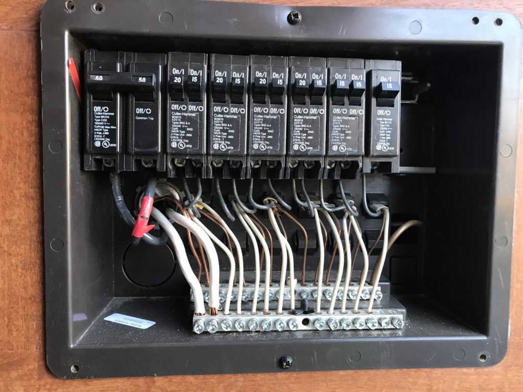
Line 1 feeds:
- Refrigerator
- Main AC Unit
- Microwave
- The converter that charges the battery
- About half of the outlets throughout the RV including all the outlets in the garage
Line 2 feeds the rest:
- The second AC Unit
- The electric water heater
- The remaining outlets around the rv
I have seen installs where people have only powered line 1, and just don’t use the line 2 circuits when boondocking, and in some of those installs, I have seen where they will move specific circuits to line 1 and/or line 2, to get power to where they want (or don’t want) when off-grid. I referred back to my solar mission statement, “everything just works”, and this didn’t work for me!
In the inverter world, there doesn’t seem to be an inverter that is specifically designed (or capable) to feed the 2 separate lines (or doesn’t cost as much as a new RV), so I started reading up on builds that used 2 inverters, with one feeding each line. That really appealed to me, it did more of what I wanted, and everything would just work (at least as long as the battery bank had power).
Many of the installs that I was following, all seemed to circle back to a couple of different manufacturers, Magnum and Victron seemed to be leading the way. Several of my friends were using Victron components with a lot of success and high praise, so I chose their equipment for the core of the system. One of the main reasons is the way these components all integrate together and share information. But we will get to that later! Lucky for me, a good friend of ours is a Victron Dealer, and I was able to get a good deal on the meat and potatoes of the system.
Our system:
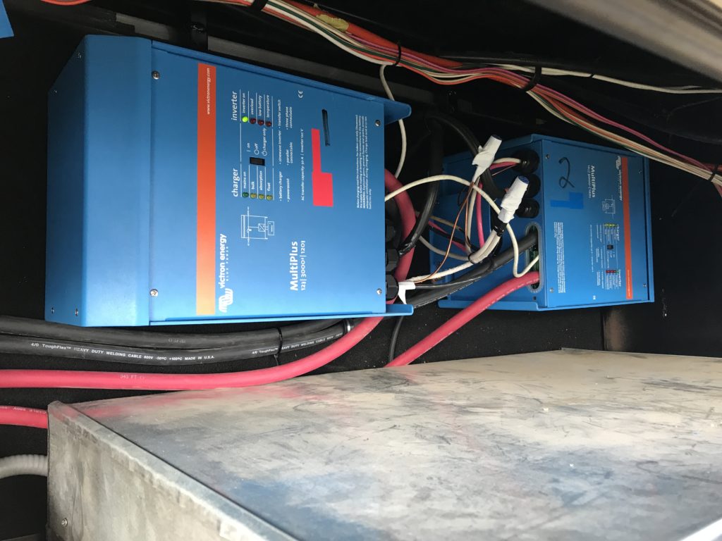
- 2 x Victron 12/3000/120-50 Multiplus
Inverter/Chargers
- These are true sine wave inverter/chargers, and take the place of the existing converter charger already in the RV. In addition, they have power assist when plugged in (or the generator is running) if there isn’t enough current coming from shore power to power the loads applied.
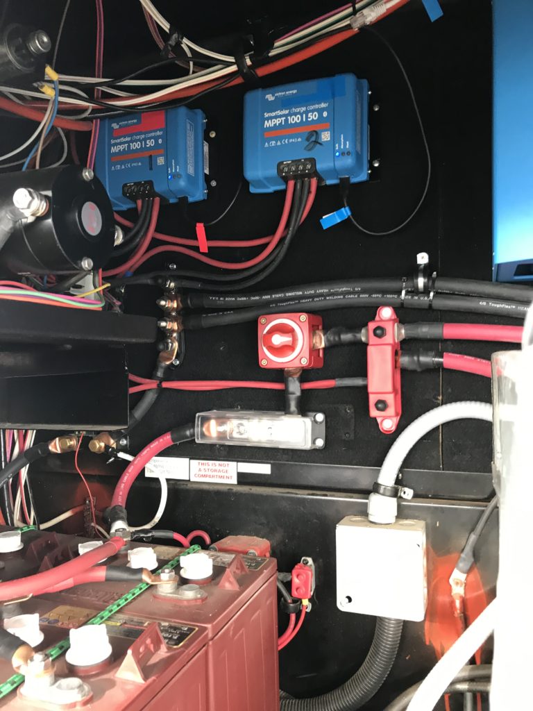
- 2 x Victron SmartSolar MPPT 100/50 Charge
Controllers with Bluetooth
- They take the energy coming in from the solar panels and convert it to stored energy in the battery bank.
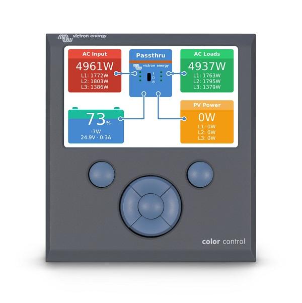
- Victron Color Control GX System Monitor (CCGX)
- This system monitor ties in all of the Victron components, and allows monitoring and control.
- Victron BMV712 Battery Monitor with Bluetooth
- This works with the shunt on the negative battery side, and measures not only the amount of energy in the battery bank, but also all usage from the batteries.
- Victron Battery Smart Sense
- Measures the battery voltage and temperature, and communicates it via Wi-Fi network. Not sure how essential this piece was, I was having some problems with battery % on the monitor, and a blog that I was reading said to add one of these, so I did!
- Victron MK3-USB for programming
Check out many of the components in our system here> https://kit.co/Roadschool/our-solar-set-up
Mounting the components was going to be tricky if I did not want to lose valuable storage space in our pass through. I wanted to mount them in the forward most compartment, above the onboard generator. But space was a premium up there, and the inverters had specific air gap requirements. The Generator has a sheet metal shroud separating it from the rest of the compartment, so I opted to cut that shroud down 6” to get the additional space I needed. I cut around the shroud, dropped it down, and put pop rivets to hold it in place.
There was a one-piece wall going all the way across the compartment that I also cut into 2 pieces, giving me a removable, accessible section for mounting the inverters and the other components. According to the Victron Manual, the inverters can be mounted horizontally or vertically, so I opted to mount them horizontally on their sides on the wall. In doing this, I met all of the required air gaps. The original wall was only ½” particle board, so to support the 70lbs that each of the inverters weigh, I added a piece of ¾” plywood across the back of the wall behind them. The charge controllers, and other various fuses, busbars and switches all mounted tightly around the other section of wall.
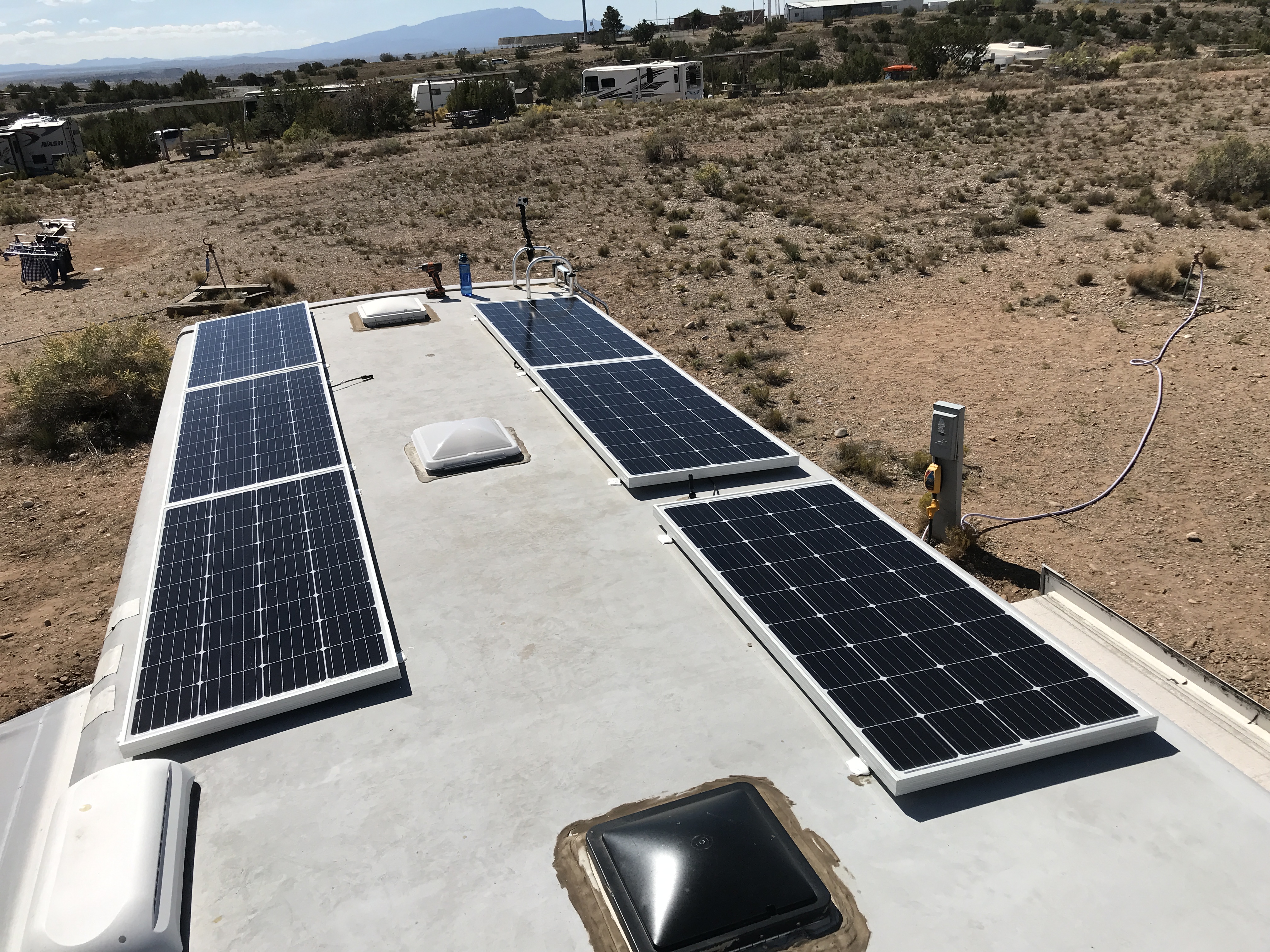
Since we are talking solar system, of course we needed solar panels. There are many different options out there for solar panels; in the end I chose to go with Continuous Resources for a few different reasons.
- First and foremost was the cost. These panels are $185 each shipped for 200 Watt Panels, and that is about as good a price you will find for that size panel, new and shipped to your door (or in our case Walgreens)!
- Next was reputation. I know many RVers (including many friends) that are using these panels and haven’t heard a single negative comment about them. One of my friends has one that was cracked during installation, and it still worked well!
- Something I liked about the particular panels I went with is that I could get the same specs in a square or rectangular panel. In the end, I went with all rectangles, but had I wanted to (or when I want to) add more panels, I can get the different shapes and make better use of my roof space.
- Check them out here: https://www.continuousresources.com/collections/solar-panels-and-hardware/products/200w-36-cell-12v-nominal-solar-panel-5-busbar?aff=34
For mounting the solar panels, I chose to use standard Z-type mounting brackets instead of the tilting brackets that I had used on the Summer House. We hadn’t tilted once, and 1 set of the tilting brackets cost more than the complete set of the Z brackets. So I went budget on the mounting brackets.
A friend of mine that helped me install most of the system taught me a great way to mount the panels. We cut squares of eternabond tape just larger than the base of the Z brackets, adhered it to the rubber roof under the bracket. We drilled pilot holes, put dicor in the hole, screwed them down and then covered the base of the bracket and surrounding roof with dicor. The eternabond tape gave it an added layer of water seal, and protected the rubber from being tore if the metal Z bracket happened to wiggle or move at all.
So now I had everything mounted, next I needed to link it all together. It’s important to have a plan in place for the wiring. When you start dealing with cutting and crimping lugs onto the cables, it gets very expensive, and you do NOT want to have to crimp, cut, and crimp again. That will cost you $5 or more for every time you miscalculate wire length and waste a wire lug.
I used a sticker wire label system. Since I was installing 2 inverters and 2 charge controllers, it was important to keep those 2 systems separate. I used red and blue wire labels to identify wiring so I wouldn’t get them confused. I also applied the same red and blue stickers on the components themselves to help keep things straight. Red was line 1 or the master system, and blue was line 2, or the slave system. (Note: for the charge controllers there is no master or slave, just 2 separate circuits that I didn’t want to get the positive or negative wires mixed up)
What tools did I use?
In addition to your normal tools, there are some other tools you might want to help you with your installation:
- Wire Cutter & Stripper, you will quickly see that the wiring for this type of installation gets expensive. You do not want to be damaging and cutting down wire more than you have to. Get yourself a good set of cutters and a stripper for heavy gauge wiring.
- Hydraulic crimping tool. I was lucky enough to have a friend helping me through most of the installation that had this crimping tool, and when he left, I struggled to find a crimping tool to finish the project that didn’t involve just beating the lugs with a hammer. Remember, those lugs are $5 or more apiece. Spend the $50 on Amazon for the crimper.
- MC4 connector crimper/tool kit was also great to have. I got it off Amazon for less than $30, and it made making my connections between the panels much easier.
- Digital Multi Meter. It doesn’t have to be super fancy, but the ability to measure resistance/continuity and both AC and DC voltage is important. This is something that any Do It Yourself RVer should have in his toolbox anyway.
The install
Let’s get this all wired up! With your plan in place, measure 3 times so you only have to cut one time! I didn’t exactly follow that rule, but it all worked out with some wire to spare!
There are many different calculators out there that will tell you the diameter and maximum lengths of wire you need for the voltages you’re going to be running, I opted to go overkill on the wiring and have the room to grow as the system evolves.
- 10 AWG wiring to connect the panels together on the roof
- 6 AWG running from the roof to the charge controllers, and onto the busbar/battery bank
- 4/0 welding cable connecting the batteries to one another, and the batteries to the inverters
- For AC wiring:
- I used 6/3 wire from the transfer switch to the inverters for the AC in (I shared the neutral and ground between the 2 inverters)
- 2 runs of 6/2 from the inverters to the RV’s AC distribution panel
There are many solutions out there for roof combiner boxes, I chose to make my own, and try to save some money this way. From Home Depot I got a waterproof electrical box about 8”x8”x6”. I covered the entire bottom of the box with dicor and screwed it down. To finish the box, I applied a bead of dicor all the way around the box. I drilled 5 holes into the box:
- 4 x Small holes, one each for wiring coming from
the panels with weather proof fits to keep the elements out
- 1” hole in the bottom leading the wires through the roof into the walls of the RV
- Inside the box the 10 AWG wires from the panels were spliced onto 6 AWG wires for its trip through the RV to the solar charge controllers
Victron components all work very well together and share information. The charge controllers, battery monitor, and smart sense are all Bluetooth individually but are all tied together via various methods that allow them to all talk to one another. I used the following wires to connect the system together:
- Cat5 network cable from the master inverter to the Color Control GX and a short Cat5 daisy-chained from the master to the slave.
- I have yet to get the Color Control GX set up on our Wi-Fi network, so when doing a firmware upgrade or a major system configuration; I do have to plug directly into the master inverter using the MK3-USB adapter. I bought a small cheap Wi-Fi adapter, and it does not work with the system. You can connect a Cat5 cable from the Color Control GX directly to your router and gain access that way as well; unfortunately my CCGX and router are not in very convenient locations to each other.
- The BMV-712 battery monitor came with its own network cable that runs from the shunt to the BMV, and I needed a VEdirect to USB cable to hook it up to the CCGX since the charge controllers fill both VeDirect ports.
- Each SmartSolar Charge controller is hooked to the CCGX via Victron’s VeDirect Cables.
- In addition to all of this wiring, the Inverters and the Battery monitor came with voltage sense and temperature sense wires that had to be connected to the battery bank accordingly.
Protection: Any electrical system, whether its AC or DC needs protective pieces in place.
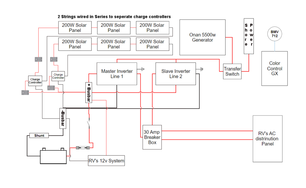
Let’s start with the solar circuit. I am running 6 x 200 watt panels configured into 2 x 3 panel legs wired in series. Each leg feeds into its own charge controller therefore I am running 2 sets (positive and negative) of wiring from the roof to the controllers. I found it more cost effective to run 2 separate smaller controllers than 1 larger controller capable of handling the amount of power coming from the panels. In addition, since the 2 strings are running independent of each other, if there is shade or lack of angle to the sun on 1 of the 2 strings, it will not hinder the energy production of the other string. For circuit protection I used:
- The panel wiring enters the RV through the roof and immediately goes into 2 x 50 amp switchable circuit breakers. Keep in mind; once the panels are in sunlight, they are producing electricity, so I used the circuit breakers in this position to give me the ability to isolate them completely from the rest of the system.
- From there the wiring runs into the solar charge controllers in the front compartment near the battery bank.
- From the charge controllers, the circuit runs into a matching set of 2 x 50 amp switchable circuit breakers. Again the point is to not only protect, but to give me a place to isolate the system if need be.
- The last leg of wiring in the solar circuit goes from the circuit breakers into the positive and negative busbars that are directly tied into the battery bank.
Let’s keep going with the DC (12 volt) system. We talked about RV electrical systems being 30 amp or 50 amp, but I failed to mention that in addition to the RV’s AC system, there is also a DC system that provides 12 volts to operate the slides, jacks, hydraulic system, lights, radio and the refrigerators control board (when running on propane it still needs 12 volts). A DC system is more similar to the type of electrical system found in an automobile. The RV’s 12 volt system has its own protection and control in place, so I did not modify it any way; I merely powered it from the positive and negative busbars from the battery bank.
The battery bank supplies DC power to the inverters that create the AC electricity that powers the RV. This part of the circuit can run extremely high amounts of electricity depending on what you are powering, so this needs substantial protection.
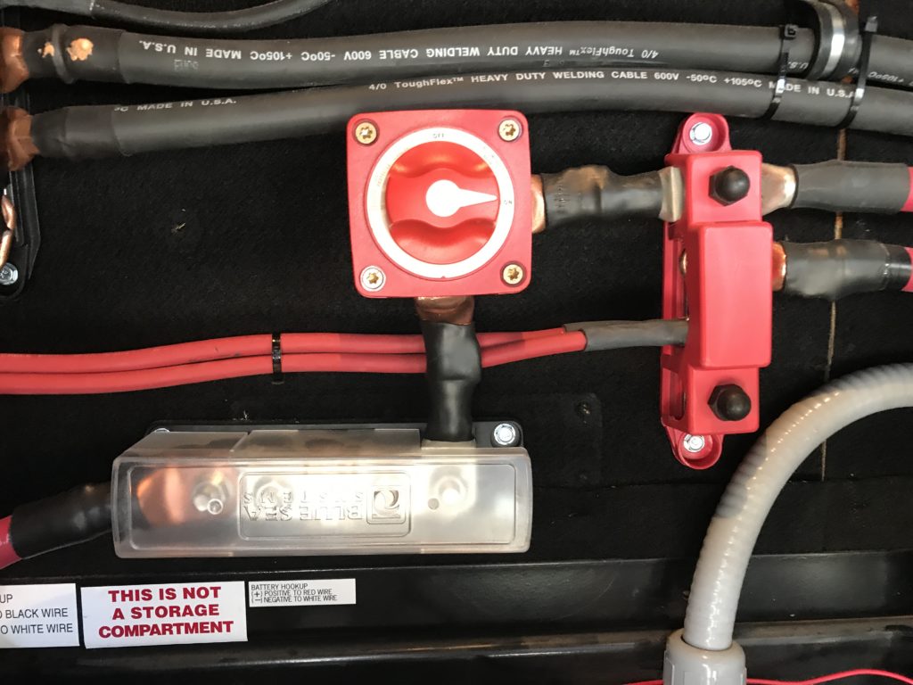
- From the Battery Bank, I ran huge 4/o wiring into a 400 amp fuse. This catastrophic failure fuse is meant to protect the wiring between the inverters and the battery bank.
- After the catastrophic fuse, there is a battery disconnect switch. This enables me to disconnect the battery bank from the positive busbar, in turn disconnecting the inverters, the solar charge controllers, and anything else connected to the bank.
- 2 separate 4/o cables run from the positive busbar directly into both inverters.
- In addition, I used an empty spot in the RV’s DC fuse panel to run power to the Color Control GX. It needs 12 volts to operate; luckily I had one empty spot, and just needed to get a 2.5 spade fuse to get it powered up.
The negative side of the DC circuit doesn’t require protection; all the protection is on the positive (hot) side. I will mention that the negative side is wired similarly to the positive site, but instead of a fuse and switch, the shunt for the battery monitor is directly between the battery bank and the negative busbar.
Now let’s talk about the AC electrical system. The AC system is like the electrical system in a house running on 120 volts. This system typically starts outside the RV as shore power at the pedestal, or coming from a generator. Our RV was equipped with a transfer switch that takes power from either shore power, or the generator, and decides which one to pass onto the RV’s panel. It’s an easy decision; as shore power has the priority. Our generator has its own built in protection system, so I did NOT add any type of breaker between it and the transfer switch. If I want to isolate the system from the generator, I just turn it off. I use a portable surge protector/EMS on my shore power cable, so I did NOT add any breaker there (if I want to isolate it, I can always unplug the cable).
I took the existing 6/3 wiring from the transfer switch and split it into the 2 inverters, but I did have to share the neutral and ground between the two.
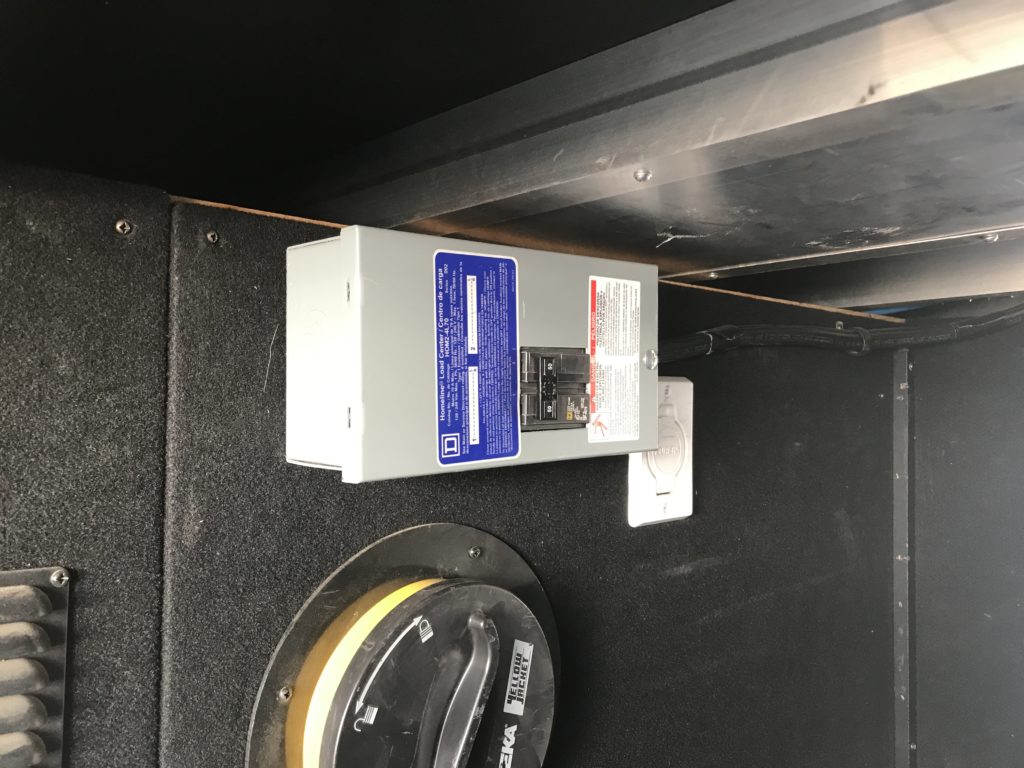
- I ran 2 strings of 6/2 wiring from the inverters (1 each) into a 2 position breaker box (2 positions, 1 for line 1, the other for line 2) mounted along the way in the pass through, and onto the RV’s AC distribution panel. This protects the RV’s electrical system, and gives me the ability to isolate one or both of the AC legs running into the panel.
- Prior to me disconnecting the power from the panel, line 1 and line 2 shared a neutral and ground via the 6/3 wiring, but since I ran 2 runs of 6/2 from the inverters, I just used empty spots on the panels ground and common bars to accommodate the extra wires.
The system is now in place, wired, and ready to go! The first thing I did was hook up my laptop to each of the inverters separately and updated the firmware. *Something to keep in mind, anytime you update the firmware on these Multiplus’, it will erase any settings you already have in place. Make sure to save these settings on your computer to re-apply them after updating! The charge controllers and the battery monitor do their updates via Bluetooth and the app on my phone and the CCGX can do it online if connected to the internet, but I have done it via micro SD card in the slot provided.
Configuring these was pretty simple; the software walked me through setting them up in parallel and was a snap. I did have to find out the specs on the Trojans to set the charge curves correctly to prevent any over or undercharging.
Something to note, with the way that the inverters are configured, if I am running my generator or plugged into 30 amp service everything works normally, but if I plug into 50 amp service I need to go in and reconfigure them to split phase, otherwise the slave inverter goes into an overload state. Rather than go in and switch programs when going between the 2, I have opted to just use an adapter, and use 30 amp services. I have the inverters set to not draw more than 40 amps per inverter, and assist if the load goes over that. I haven’t had any problems with this configuration, and have been running this way since being fully online.
Hi , I found your solar setup online, very interesting. I have been thinking on doing the same. I was wondering if you dont mind ,what your total cost was.
Thanks
Ivan from Canada harmoney46@hotmail.com
I honestly dont remember, but a great resource is my friends at https://panelsupsolar.com/
I understand that you had people helping you. It looks like a system that we can use on our class A.
Could you tell me what you spent in panels, cables, connections, switches, batteries, etc.? Labor is something else I need to figure.
Yours have been the best system and most understandable.
Appreciate any and all help.
Thanks Darlene
Darlene I honestly dont remember, a grear resource is my friends over at Panels up Solar. https://panelsupsolar.com/
Very good solar discussion, As electricity is not your profession, your article is very impressive. Having retired from coal fired 1740 megawatt power plant as a maintenance electrician this should be cake. To make this worse for me, I was in charge of the massive battery back up systems. I would have paralleled the collectors (solar panels) and chargers on one bus. Is there a specific reason you didn’t, are your chargers incompatible or did YOU need the systems divided for ease. I am not knowledgeable on collectors, but they should act just like another charger I would think.
I am living in my RV full time and will be purchase/installing a system early 2022. My problem is I will be mostly in AZ dessert during the summer. Trying to collect enough power during the day to run 2 Air Conditioning units, a non anhydrous ammonia refrigerator (standard house 120V 4amps fridge) and the rest of the RV with outside accessories is becoming a challenge to design and still keep it on the RV. An insight of how much you use air conditioning would be helpful.